Home > Blog > Piezoelectric vs Piezoresistive Pressure Sensors: Which One for Your Application
Piezoelectric vs Piezoresistive Pressure Sensors: Which One for Your Application
Piezoelectric and piezoresistive pressure sensors are two commonly selected types of pressure sensors in industrial processes. Differences in their operating principles result in distinct advantages for each. Piezoelectric sensors have higher sensitivity and faster response times, enabling them to provide relatively precise pressure measurements. Therefore, piezoelectric pressure sensors are used to measure dynamic pressure. Piezoresistive sensors have slower response times and require some time to adapt to pressure changes. However, they offer higher accuracy for static measurements.
If your application requires both stable baseline readings and the ability to capture rapid transient changes, then a high-frequency piezoresistive sensor (SI-90) is the ideal choice.
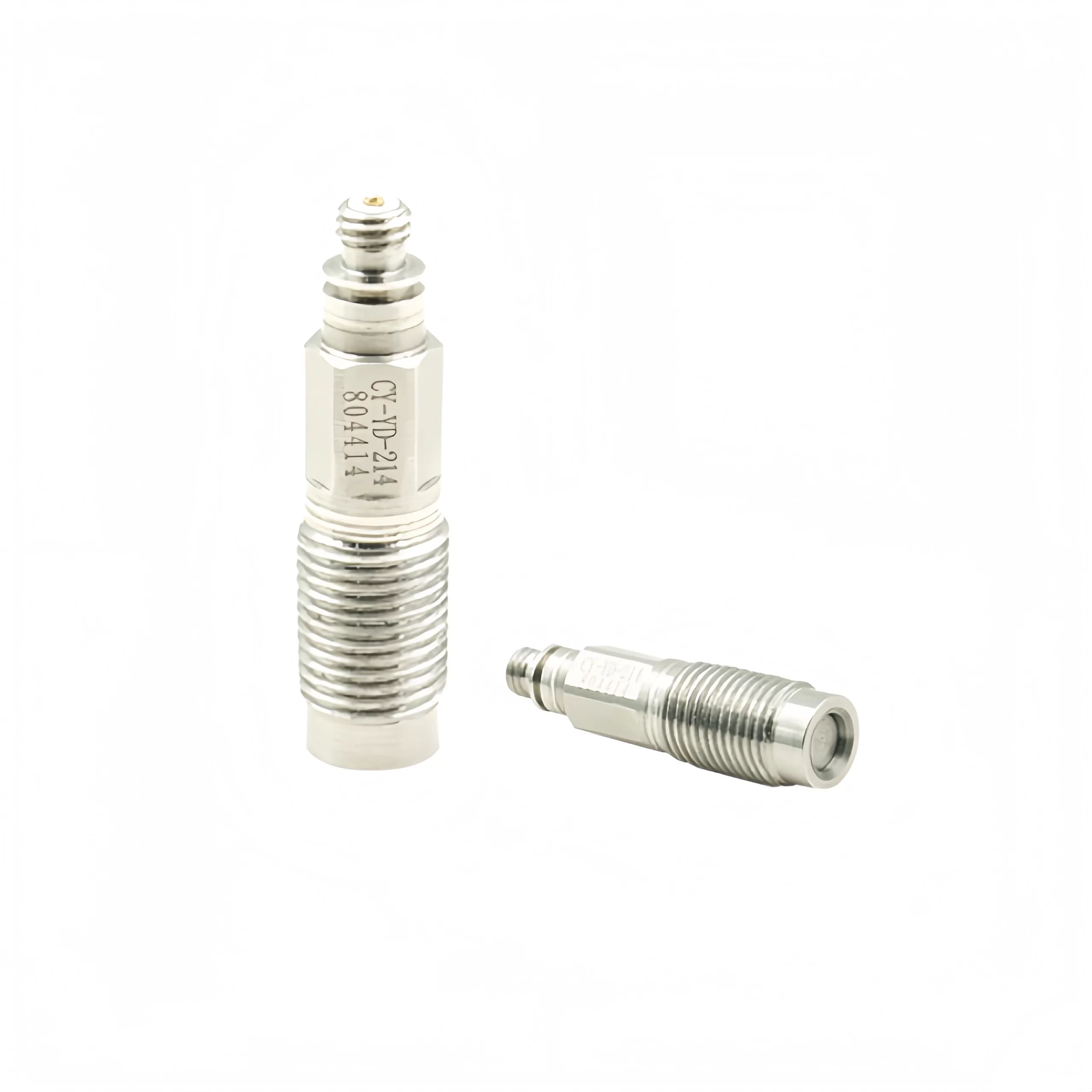
A piezoelectric pressure sensor is a type of sensor that measures pressure based on the piezoelectric effect, converting pressure into an electrical charge output signal. Piezoelectric pressure sensors typically use quartz or piezoelectric ceramics as the crystal. They are commonly used for measuring high temperatures, rapidly changing pressures, and minute pressure fluctuations.
Sensor Structure and Operating Principle
A piezoelectric pressure sensor typically consists of a piezoelectric element, electrodes, and packaging materials. The piezoelectric element converts pressure into charge; the electrodes collect the charge and convert it into an electrical signal; and the packaging materials protect the piezoelectric element and isolate it from the external environment.
When pressure is applied to the piezoelectric element, the crystal lattice structure within the piezoelectric material deforms, causing a buildup of charge on its surface. The amount of this charge is proportional to the applied pressure. Through the electrodes connected to the piezoelectric element, this charge can be collected to form an electrical signal proportional to the pressure. This electrical signal is typically very weak and must be processed by an amplification circuit before it can be used in practical applications.
Signal Processing and Amplification
The electrical signal output by a piezoelectric pressure sensor is typically a charge signal with a very small amplitude, which must be converted into a voltage signal by a charge amplifier. Charge amplifiers typically feature a high-impedance input to prevent signal loss. The amplified voltage signal can be further processed—for example, through filtering or calibration—to improve signal quality and accuracy. The quality of signal processing directly affects the sensor’s accuracy and reliability.
However, it is important to note that piezoelectric pressure sensors are capable of measuring dynamic pressure but are generally not suitable for static pressure measurements. Kistler’s technical documentation also points out that charge-output (PE) piezoelectric pressure sensors exhibit slight drift under static loading, whereas piezoresistive sensors exhibit virtually no drift. In contrast, sensors based on the piezoresistive principle exhibit virtually no drift during operation.
On the other hand, the advantages of piezoelectric sensors are also evident: extremely fast response, compact design, high-temperature resistance, and strong overload capacity. Therefore, they are the preferred choice for measurements such as shock waves, combustion pressure, and high-frequency pulsations.
What Is a Piezoresistive Pressure Sensor?
A piezoresistive pressure sensor is a device that measures pressure based on the piezoresistive effect. When pressure is applied to the sensor, its internal resistance changes; the pressure value is determined by monitoring these resistance variations. A classic piezoresistive pressure sensor consists of a thin diaphragm, a pressure-sensitive resistor, and a Wheatstone bridge. The diaphragm is typically made of materials such as monocrystalline silicon or polycrystalline silicon.
Piezoresistive pressure sensors exhibit virtually no drift, making them the preferred choice for measuring static pressure.
Sensor Structure and Operating Principle
The core of a piezoresistive pressure sensor is the piezoresistive effect of semiconductor materials. Its key component is a silicon diaphragm. The sensor detects external pressure through a stainless steel corrugated diaphragm; silicone oil transmits the pressure to the semiconductor chip, causing a change in resistance that is then output via leads. The sensor is connected to a Wheatstone bridge circuit; when pressure changes disrupt the bridge balance, a voltage signal proportional to the pressure is output, enabling pressure detection.
Sensitive Chip: A monocrystalline silicon diaphragm manufactured using MEMS (Micro-Electro-Mechanical Systems) technology, with resistive strips integrated onto the silicon diaphragm to directly sense pressure.
Stainless Steel Corrugated Diaphragm Housing: Used to isolate the sensor from the external environment and transmit pressure, while protecting the internal chip from corrosion.
Silicone oil medium: Filled between the corrugated diaphragm and the silicon chip, it serves as the pressure transmission medium, ensuring uniform pressure transfer.
Leads and packaging: These transmit the resistive signal outward, while the packaging technology creates a vacuum chamber structure to enhance environmental adaptability.
The sensor is typically connected to a Wheatstone bridge circuit. Changes in pressure cause the bridge to become unbalanced, and the output voltage is proportional to the pressure, thereby enabling pressure measurement.
Piezoresistive pressure sensors offer good low-frequency performance and high linearity. However, the sensor’s force-sensitive material is highly susceptible to environmental factors such as temperature and humidity, so temperature compensation is required.
Quartz or piezoceramic crystal generates an electric charge proportional to pressure
Pressure bends a silicon diaphragm and changes the resistance of a Wheatstone bridge
Static pressure
Not suited to long-term static measurement: output drifts under constant load (charge type); IEPE types have a low-frequency cut-off
Yes, true static (DC) measurement with virtually no drift
Dynamic / frequency response
Excellent: very high natural frequency, suited to shock, blast and combustion pressure
Standard types: about 1 ms response. High-frequency types: bandwidth up to 20–200 kHz
Rise time
Microseconds
Standard: milliseconds. High-frequency: down to ≤1 µs
Output signal
Charge (pC) or IEPE voltage
mV/V, 0–5 V, 0–10 V, 4–20 mA or digital
Signal conditioning
Needs a charge amplifier or IEPE constant-current supply, plus low-noise cable
Built-in electronics; connects directly to a PLC or data acquisition system
Static accuracy
Not designed for static accuracy
Typically ±0.1% to ±0.5% FS
Temperature
High tolerance; quartz designs suit hot environments
Needs temperature compensation; very hot media need a cooling tube or siphon
Overload & shock
Very robust
Good; check the rated overload and burst pressure
Size & mounting
Can be very small; fits tight mounting holes
Industrial types usually G1/4, G1/2 or 1/4″ NPT
System cost
Higher (sensor plus amplifier and cabling)
Lower for standard types; high-frequency types cost more
Typical applications
Blast and shock waves, engine combustion, ballistics, aerodynamic testing
Process control, hydraulics, cryogenics, test benches, and transient monitoring that also needs static readings
Sino-Inst models
—
SI-1180 (general purpose), SI-90 (high frequency, up to 200 kHz)
Do You Really Need a High-Frequency Sensor?
We frequently receive inquiries from customers requesting “fast response.” This term has two distinct meanings: response time and response frequency (bandwidth).
First, response time. Response time refers to how long it takes for the output to catch up after a sudden change in pressure, measured in milliseconds. Standard pressure transmitters typically have a response time of 1–5 ms, which is generally sufficient for process control, pneumatic, and hydraulic applications.
Response frequency (also called frequency response or bandwidth) refers to the range of pressure fluctuation frequencies that a sensor can accurately track, measured in hertz (Hz). For example, “0–20 kHz” means that the sensor’s output will still accurately reflect pressure changes even when the pressure fluctuates up to 20,000 times per second. Signals such as blast shocks, combustion pressure, and thermoacoustic oscillations—which change on the microsecond scale—require a bandwidth ranging from a few kHz to several hundred kHz.
As a rough rule of thumb: a response time of 1 ms is roughly equivalent to a bandwidth of 0.35 kHz. If you only need millisecond-level response, a standard transmitter will suffice; if you need to clearly observe the pressure waveform itself, then a high-frequency sensor is required.
For example, we once received the following inquiry from a customer:
A Malaysian instrumentation distributor requested a response time of less than 3 ms, with a range of 0–500 psia and a medium temperature of 150°C. He had originally considered a high-frequency model, but after our evaluation, we recommended a basic pressure transmitter with 0.1% accuracy and a response time of <3 ms—which fully met the requirements at a significantly lower cost.
A laboratory at a university in South Korea was conducting pneumatic pressure control experiments and inquired about the SI-90. In reality, a response time of 2–3 ms was sufficient, and they ultimately resolved the issue using the general-purpose SI-2088.
So, before selecting a model, ask yourself: Do I need “timely readings” or do I need to “clearly see the waveform”? For the former, a standard transmitter will suffice; only the latter requires a high-frequency sensor.
When to Choose a Piezoelectric Pressure Sensor
Piezoelectric pressure sensors are widely used in applications requiring real-time dynamic pressure monitoring.
Cryogenic liquid oxygen measurement: -200 to 80°C, 0–20/50/150 bara absolute pressure, accuracy 0.1%, response frequency approximately 2.5 kHz; the SI-2088 liquid oxygen model was used and has been successfully deployed.
Germany, Industrial Furnace Equipment: The SI-2088 was used for liquid nitrogen pressure testing. The customer commented, “The SI-2088 was great for the purpose,” and later inquired about a high-frequency version with a response rate of approximately 1 kHz.
United Kingdom, Test and Measurement Equipment: Used for liquid hydrogen and liquid nitrogen measurements. The customer had previously purchased the SI-2088 and specifically requested to continue using it, noting that it “worked well.”
If an application requires both static pressure measurement and the detection of pressure fluctuations above a few kHz, the high-frequency piezoresistive pressure sensor SI-90 is a suitable choice.
Can piezoelectric elements be used as pressure sensors? Why hasn’t piezoelectric technology become more widespread?
First, piezoelectric elements can be used in pressure sensors—specifically, piezoelectric pressure sensors. They offer irreplaceable advantages in measuring dynamic pressure. They are commonly used in applications requiring ultra-high-frequency response, self-powered monitoring, and extreme high-temperature transient measurements.
However, piezoelectric technology cannot measure static pressure, which limits its application in general industrial settings. Furthermore, piezoelectric pressure sensor systems are more complex and have higher production costs. For these reasons, they have not become widely adopted.
How do piezoelectric pressure sensors compare to piezoresistive sensors for dynamic measurements?
Both piezoresistive and piezoelectric pressure sensors can measure dynamic pressure, but they differ in their measurement focus.
Piezoelectric pressure sensors: They have a high natural frequency and short rise time, with a frequency response ranging from 0.1 Hz to 500 kHz. They are resistant to high temperatures and shock, making them suitable for extremely fast transient signals such as explosion shock waves and combustion pressures. However, they cannot measure static pressure over long periods because the signal drifts, and they require a charge amplifier
Piezoresistive pressure sensors: These sensors offer good low-frequency performance and high linearity, with a frequency response ranging from DC to 150 kHz. They can simultaneously measure both static base pressure and dynamic fluctuations, and their output can be directly connected to a data acquisition system. The drawback is that they are significantly affected by temperature, requiring temperature compensation; cooling is also necessary in high-temperature operating conditions.
Master dynamic pressure sensor technology. We’ll guide you through the piezoelectric principle, fast response characteristics, and industrial applications. What is a Dynamic Pressure Sensor? Dynamic pressure sensors are specifically designed to measure dynamic pressure with high frequency variations and steep pressure waveform rise times. They measure instantaneous pressure changes, not “average” pressure. Dynamic pressure sensors … Read more
In fields such as military engineering, explosive testing, oil and gas exploration, materials and geotechnical mechanics, trauma medicine, and hydraulic power testing, the precise measurement of high-frequency transient pressure waveforms places stringent demands on the dynamic performance of sensors. The SI-90 high-frequency dynamic pressure transmitter is designed specifically for these applications. Through micromachining technology, it achieves … Read more
What is a Pressure Transducer? It is often called a pressure transmitter. An absolute Pressure Transducer is a device that measures the pressure relative to 0 Pa. Then, a Gauge Pressure Transducer is an instrument that measures the pressure with atmospheric pressure as the reference point. A Differential Pressure Transducer measures the difference between pressures … Read more
You need to measure pressure, so you are going to purchase a pressure transmitter. Then you will find that there are many types of pressure sensors on the market. You will see capacitive pressure transmitter, MEMS pressure sensor, absolute pressure transmitter, differential pressure transmitter, pressure transmitter diaphragm type, 4-20mA pressure transmitter and many more. So … Read more
What Is a Pressure Snubber? A pressure snubber, also known as a pressure buffer, is a device designed to prevent intense fluid pulses and protect pressure instruments from damage. It is suitable for pressure systems where the medium being measured experiences pressure spikes, intense pulses, and rapid fluctuations. It is often used in conjunction with … Read more
Industrial liquid oxygen is a colorless and odorless liquid oxygen with low temperature and flammable properties. In the fields of petroleum, chemical industry, and medical treatment, liquid oxygen is widely used in the production process. Its leakage may cause serious harm to operators and equipment. Real-time monitoring of the pressure of liquid oxygen tanks and … Read more
Zhang Wei, possesses 20 years of experience as an automation instrumentation engineer, specializing in the research, design, installation, commissioning, and maintenance of automation instruments.
Face to various instrument communication protocols (such as Modbus, Profibus, etc.), with solid hardware circuit design and software programming skills (proficient in C language and PLC programming). Has extensive project experience; projects he has led and participated in have all achieved outstanding results, improving product accuracy, reducing costs, and increasing production efficiency.
Possesses excellent communication and coordination skills and a strong team spirit, enabling him to quickly respond to customer needs and provide high-quality automation instrumentation solutions.
Want to see more of our engineering guides in Google Search? Add Sino-Inst as a preferred source.