
RTD Wiring: 2-Wire vs 3-Wire vs 4-Wire PT100 Diagrams
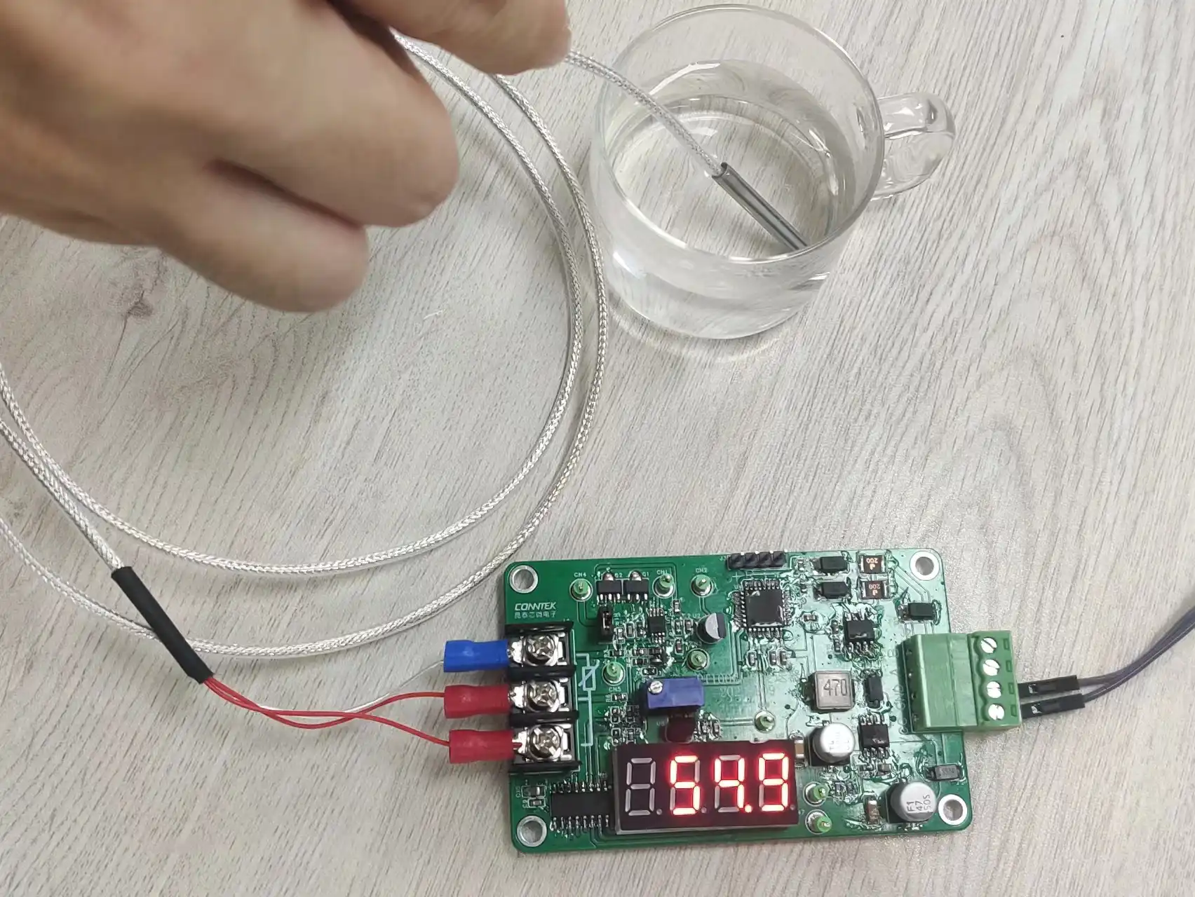
There are three options for resistance temperature detector (RTD) wiring: 2-wire, 3-wire, and 4-wire. The key difference lies in whether the measurement error caused by lead resistance can be eliminated. Simply put: 2-wire systems have large errors and are largely obsolete; 3-wire systems are commonly used in industry; and 4-wire systems offer laboratory-grade precision.
Why are there these differences in wiring? A PT100 has a resistance of 100 Ω at 0°C, and its resistance changes by approximately +0.385 Ω/°C as the temperature changes (IEC 751 standard). The connecting wires themselves also have resistance (typically 0.1 to several Ω); if this resistance is included in the measurement, it will cause a positive temperature deviation. Therefore, when purchasing a resistance temperature detector (RTD), clearly identify the wiring configuration you need; selecting the appropriate configuration can minimize measurement errors.
2-Wire vs 3-Wire vs 4-Wire RTD
The main difference between these three RTD wiring configurations lies in how the resistance of the compensation leads affects measurement accuracy.
The principle behind RTD temperature measurement is that changes in temperature cause changes in resistance, which the instrument then converts to temperature. However, a key issue is that the wires connecting the RTD to the instrument have their own resistance. The longer and thinner the wires, the greater their resistance, and the more significant the measurement error becomes.
Therefore, different wiring configurations are used to offset or minimize the errors caused by lead resistance, thereby meeting varying accuracy and cost requirements.
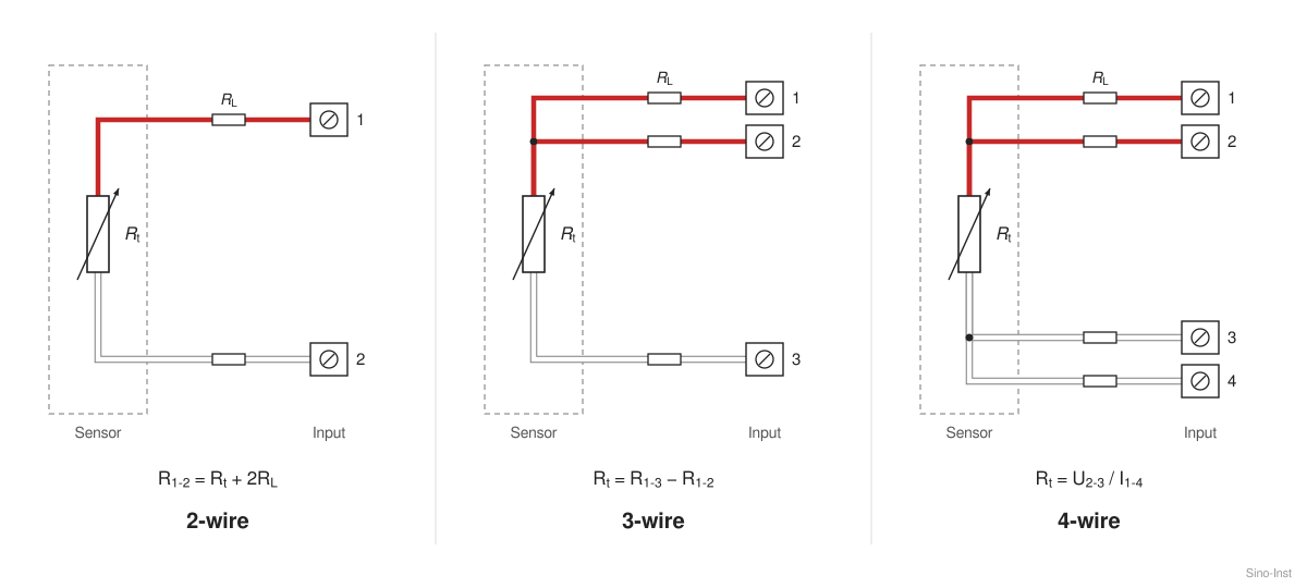
| 2-Wire RTD | 3-Wire RTD | 4-Wire RTD | |
|---|---|---|---|
| How it is wired | One lead on each end of the element | One lead on one end, two leads on the other end | Two leads on each end: one pair carries current, one pair measures voltage |
| What the instrument measures | Rt + 2 RL | Rt, assuming all three leads have equal resistance | Rt = V ÷ I (leads carry almost no current in the sense loop) |
| Lead resistance compensation | None | Partial: cancels lead resistance, but not any mismatch between leads | Full: cancels lead resistance and lead mismatch |
| Example error (Pt100, 10 m of 0.5 mm² copper per lead) | About +1.8 °C (0.7 Ω loop) | About 0.03 °C (3 % lead mismatch) | Negligible |
| Cable length | Short runs only, a few metres, or use a Pt1000 to reduce the error tenfold | Long runs, provided all three leads are the same gauge and run in the same cable | Long runs; length no longer affects accuracy |
| Accuracy class it can support (IEC 60751) | Class B or wider, with the lead offset calibrated out | Class B and Class A | Class A and AA; needed when Class A must be verified at the connection end |
| Wire colors (IEC 60751) | Red, White | Red, Red, White | Red, Red, White, White |
| Cost and complexity | Lowest | Moderate: industry default | Highest: extra conductor and a 4-wire input |
| Typical receiving instruments | Simple controllers, panel indicators, OEM and HVAC equipment | Head-mount transmitters, PLC RTD input cards, temperature controllers | Precision transmitters, data acquisition systems, calibration and lab meters |
| Best for | Short leads where a small offset is acceptable | Most industrial process measurement | Custody transfer, calibration, R&D and any Class A requirement over long cable |
| Main limitation | Error grows with every metre of cable and with ambient temperature on the cable | Assumes equal leads; corroded terminals or mixed cable break the compensation | Needs a true 4-wire input; a 3-wire input wastes the fourth lead |
2-Wire RTD Wiring Diagram
In a 2-wire connection, one wire is connected to each end of the RTD, for a total of two wires connected directly to the instrument. This is the simplest and least expensive wiring method.
The total resistance measured by the instrument = the resistance of the RTD itself + the resistance of the two wires. The wire resistance is directly factored into the temperature measurement, resulting in an overestimated reading.
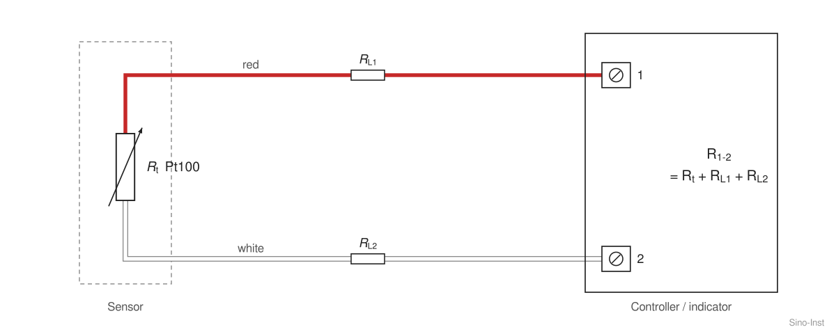
Example:
At 100°C, a Pt100 RTD has a resistance of approximately 0.385 Ω per 1°C. If the total wire resistance is 2 Ω, the temperature measurement error is approximately 5.3°C; the longer the wires, the more extreme the error becomes.
Suitable scenarios: extremely short leads (within a few meters), low accuracy requirements, non-critical locations (such as ambient temperature or cabinet temperature), and scenarios where cost is a major concern.
3-Wire RTD Wiring Diagram
A 3-wire connection consists of one wire at one end of the RTD and two wires at the other end, for a total of three wires. Key requirement: All three wires must be of the same material, gauge, and length, and must be installed in the same environment (to ensure equal resistance).
By using a bridge circuit, the resistance of the two lead wires is placed in adjacent bridge arms to cancel each other out; under ideal conditions, this can completely eliminate lead wire error.
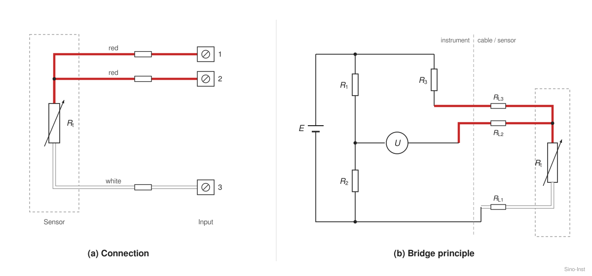
Advantages: Sufficient accuracy, moderate cost, and ease of wiring and installation; it meets the needs of the vast majority of industrial sites and is currently the preferred choice for factories and workshops.
Applicable Scenarios: Factory assembly lines, HVAC, chemical processing, metallurgy, PLC temperature data acquisition, temperature controllers, and standard operating conditions where wire lengths are within tens of meters.
4-Wire RTD Wiring Diagram
There are two wires on each end of the RTD, for a total of four wires. These are divided into two groups: two carry a constant current (power supply), and two measure voltage (sensing)—commonly known as the Kelvin four-wire measurement method.
The current leads are used solely for power supply; the voltage drop across them is not included in the measurement. The voltage leads connect to a high-impedance instrument and carry virtually no current. The resistance of the connecting wires does not cause a voltage drop, so the instrument reads the pure resistance value of the RTD itself.
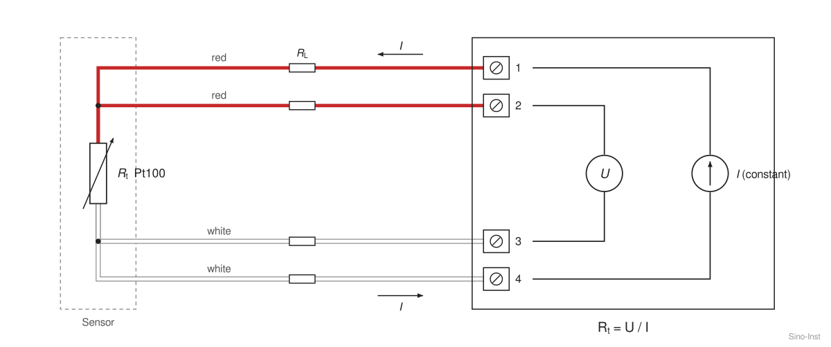
Advantages: Theoretically zero lead error and strong resistance to interference. It maintains extremely high accuracy even with very long leads or extreme environmental temperature differences, making it the standard for metrological-grade and precision temperature measurement.
Applications: Laboratory metrological calibration, pharmaceuticals, semiconductors, high-precision reactors, and special operating conditions requiring the highest accuracy and extremely long lead wires.
How to Choose
Prioritize the 3-wire system: In 90% of industrial scenarios, the 3-wire system offers the best balance of accuracy, cost, and wiring complexity; there is no need to blindly pursue the 4-wire system.
Wires Must Be “Three-Identical”: For both 3-wire and 4-wire systems, the wires must be of the same model, the same length, and laid in the same manner—stranded wiring is preferable—to avoid additional errors caused by temperature differences.
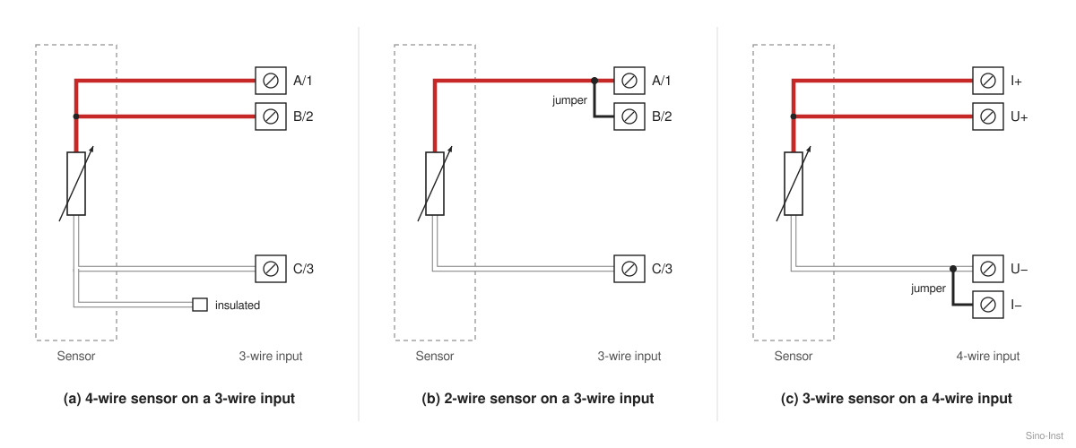
Wire Configuration Must Match: The wire configuration set on the instrument must match the RTD wiring; for example, hard-wiring a 4-wire sensor to a 2-wire instrument will still result in errors.
Recommended RTD Sensors and Transmitters
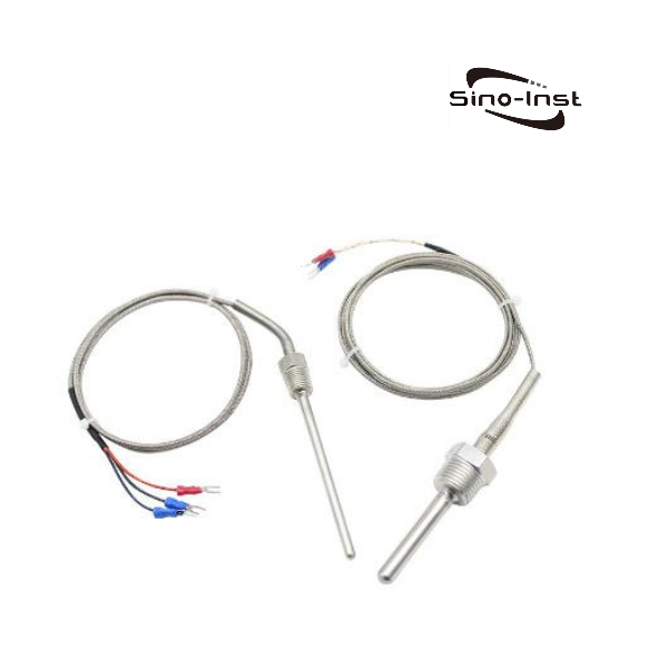
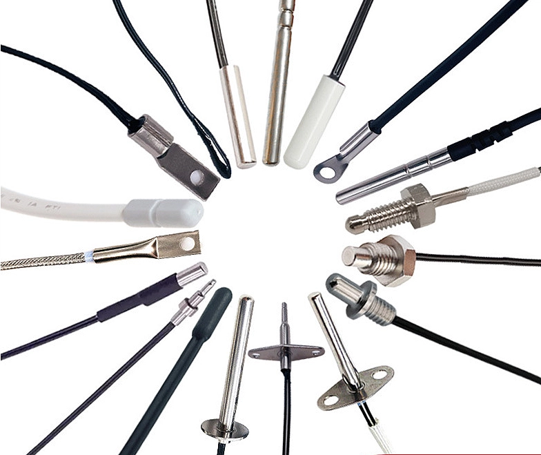
3-wire Pt100 probe for -200 to 600 °C. Probe length, thread and cable length are made to order.
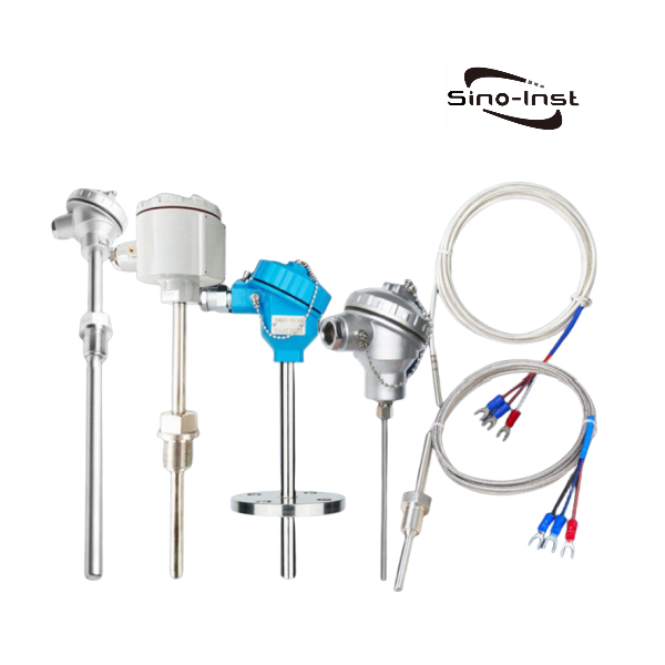
Pt100 and Pt1000 assemblies, single or dual element, with threaded, ferrule, flange and explosion-proof mounting.
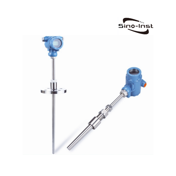
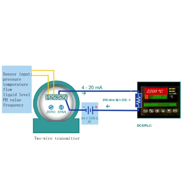
Converts a Pt100 or thermocouple input to a two-wire 4–20 mA signal, with a local display. Explosion-proof version available.
Dual-Element (Duplex) RTD Wiring
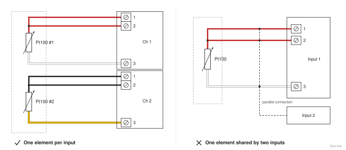
Dual-Element RTDs consist of two sensitive, stable platinum resistance elements and are used in process applications where two sets of display instruments, recording instruments, or control instruments are required to simultaneously measure the temperature at the same location, or where a backup temperature-sensing element is needed.
Each element within a dual-element RTD can be wired in the same manner as a single RTD. For dual-element sensors, the number of leads is doubled accordingly.
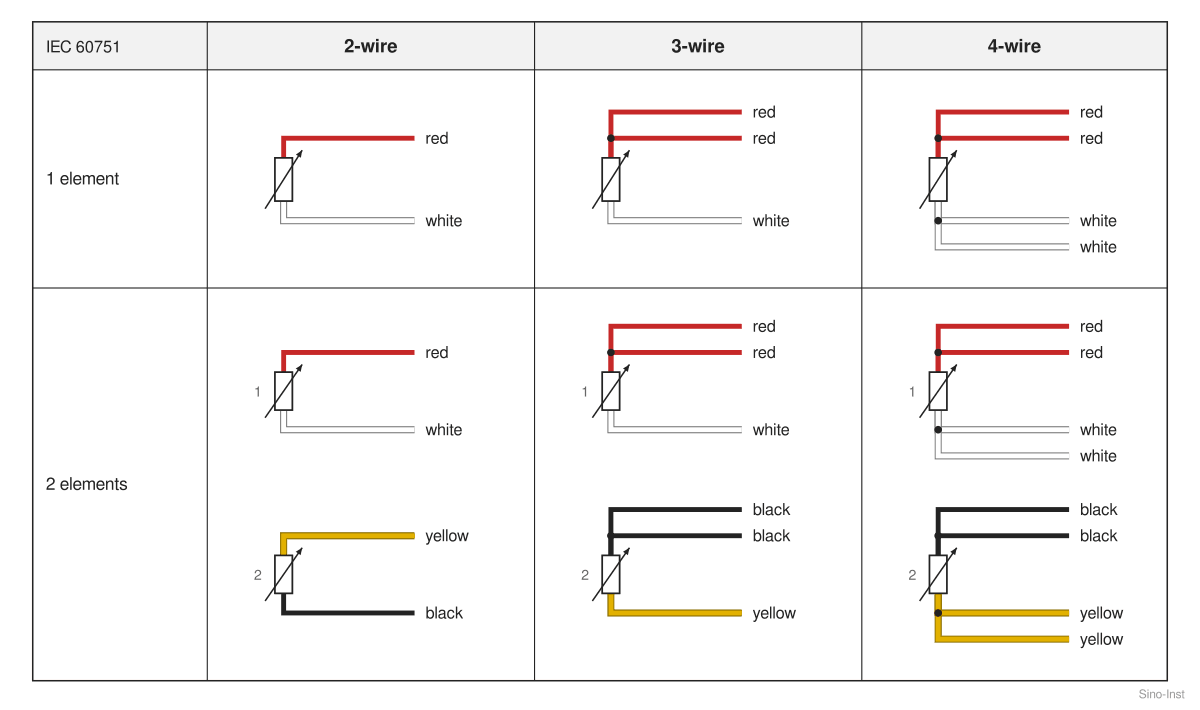
In a 2-wire connection, two wires are connected to the element, and the measured resistance includes the lead resistance. Each element has two wires, so a dual-element RTD has a total of four external wires.
In a 3-wire connection, three wires are connected to one end of the element, and a common wire is connected to the other end. Each element has three wires, so a dual-element Pt100 has six external wires.
In a 4-wire connection, two wires supply a constant current, and two separate wires measure the voltage across the element. Each element has four wires, so a dual-element RTD has eight external wires. This configuration is less common but is essential for high-precision metrology and laboratory applications.
Connecting an RTD to a Temperature Controller, PLC or Transmitter
Resistance Temperature Detectors (RTDs) output a signal based on changes in resistance and cannot be directly connected to standard PLC analog modules. There are two main connection methods: first, connecting directly to a temperature controller or the PLC’s RTD input module; second, connecting to a temperature transmitter first to convert the signal to 4–20 mA before sending it to the PLC. For short-distance wiring within a control cabinet, RTD modules are generally used; for long distances or in environments with significant on-site interference, it is more reliable to install the transmitter inside the probe junction box.
Method 1: Direct Connection to a Temperature Controller or PLC RTD Module
- Wire according to color. For a 3-wire configuration: Connect the wire of a different color to A, and the two wires of the same color to B and b. For a 4-wire configuration: Connect one pair of wires of the same color to I+ and M+, and the other pair to M− and I−. RTD terminals on temperature controllers are often labeled with numerical codes; refer to the instrument or module manual for specifics.
- Set the input type. On the temperature controller, select “Pt100” from the menu; be careful not to select “JPt100” (the two differ by approximately 1.7 °C at 100 °C). On the PLC, select “Pt100” and the corresponding wiring configuration in the setup. A mismatch between the wiring configuration and the actual wiring is the most common cause of reading errors.
- Power-on check. The reading should be close to the current ambient temperature.
Method 2: Connecting to the PLC via a Temperature Transmitter
- Connect the RTD to the transmitter using a 3-wire or 4-wire connection.
- Connect the transmitter to the PLC’s analog input. Two-wire circuit: 24 V+ → Transmitter + → Transmitter − → PLC AI+ → AI− → 24 V−.
- PLC Temperature Conversion: T = Lower Limit + (I − 4) ÷ 16 × Measurement Range. For example, for a range of −50…200 °C, 12 mA corresponds to 75 °C.
As an important temperature measurement device, the resistance temperature detector (RTD) achieves precise temperature measurement by measuring how resistance changes with temperature. Different RTD wiring configurations are suitable for different applications, and selecting the appropriate wiring method can improve measurement accuracy and stability, thereby meeting the temperature measurement needs of various industrial and scientific fields.
If you are unsure whether to choose a two-wire, three-wire, or four-wire system, please contact our sales engineers in advance to discuss the details of your operating conditions.
Further Reading


Zhang Wei, possesses 20 years of experience as an automation instrumentation engineer, specializing in the research, design, installation, commissioning, and maintenance of automation instruments.
Face to various instrument communication protocols (such as Modbus, Profibus, etc.), with solid hardware circuit design and software programming skills (proficient in C language and PLC programming). Has extensive project experience; projects he has led and participated in have all achieved outstanding results, improving product accuracy, reducing costs, and increasing production efficiency.
Possesses excellent communication and coordination skills and a strong team spirit, enabling him to quickly respond to customer needs and provide high-quality automation instrumentation solutions.
Want to see more of our engineering guides in Google Search? Add Sino-Inst as a preferred source.