Home > Blog > RF Capacitance Level Transmitters for Turbine Oil Tanks
RF Capacitance Level Transmitters for Turbine Oil Tanks
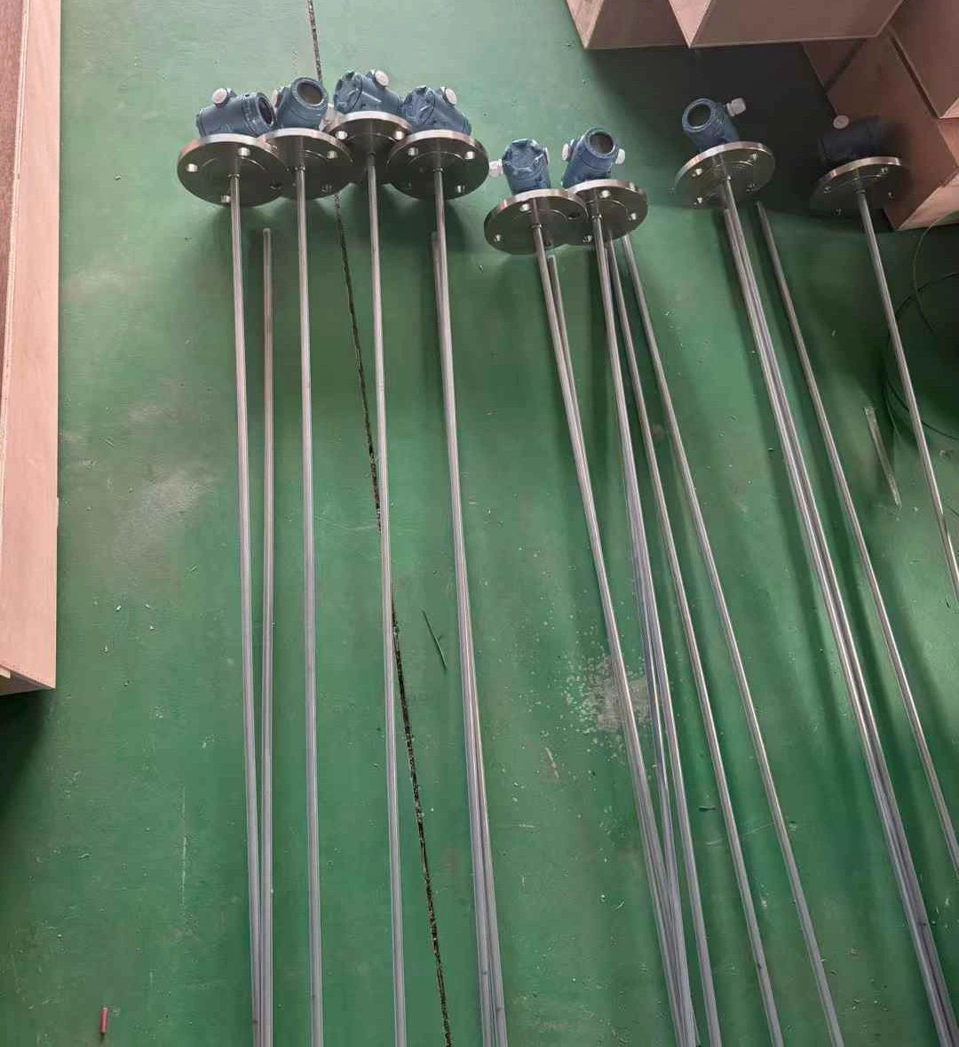
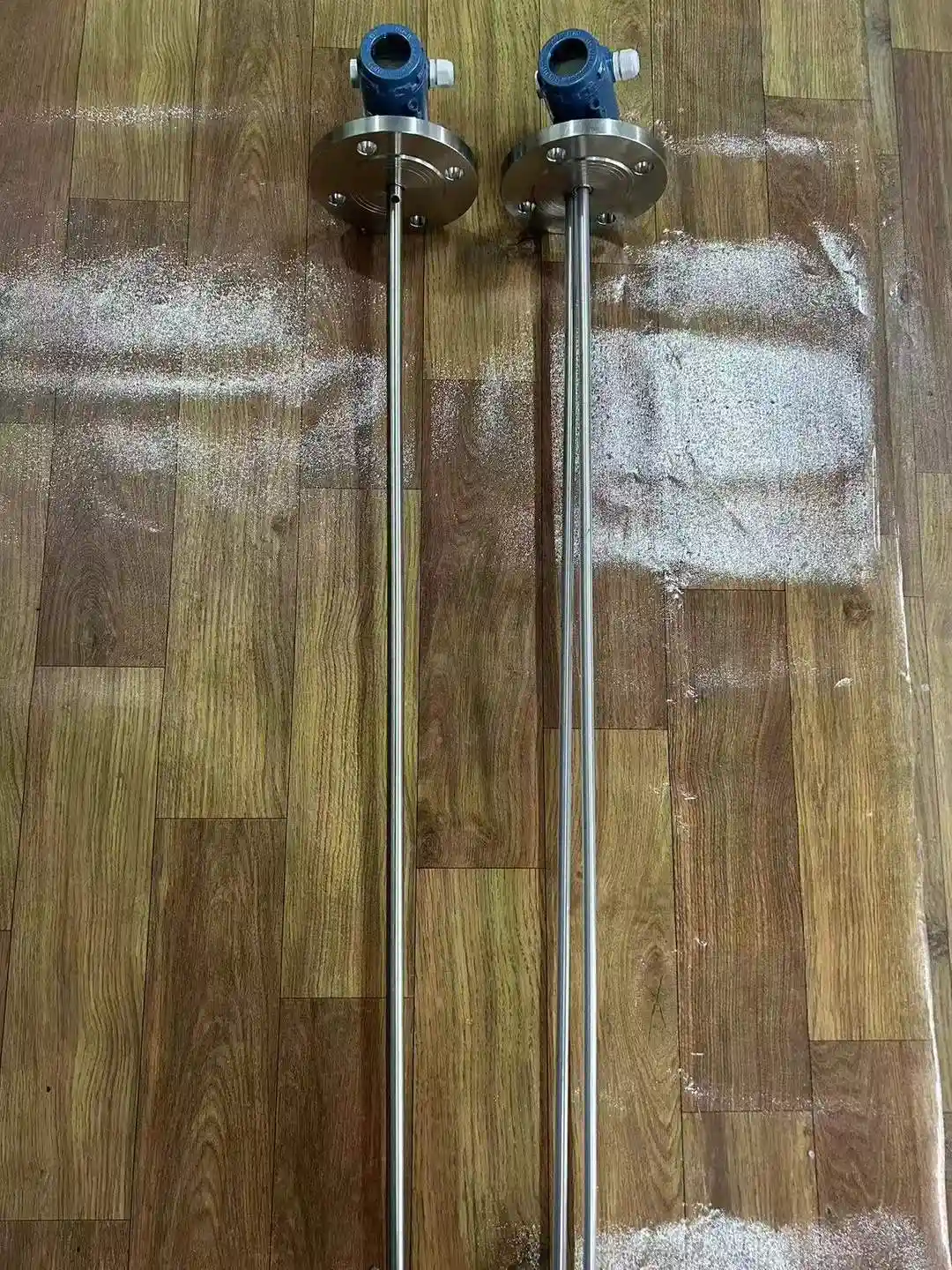
For a turbine oil tank level measurement project, the client specified an RF capacitance level transmitter with a 700mm coaxial rod probe and PTFE insulation. The operating conditions are 200°C and 24 bar, with a 4–20 mA + HART output and a 1.5″ BSP threaded connection.
An assessment based on application experience confirms that an RF capacitance level transmitter configured with a coaxial probe and PTFE insulation is suitable for these 200°C operating conditions. However, the signal output and thread size require final verification before project implementation.
Below, we outline the configuration specifications for the RF capacitance level transmitter, covering the probe, insulation material, temperature and pressure ratings, output, and process connection.
Coaxial rod probe (switch to coaxial cable probe for longer ranges)
Probe Material
316L stainless steel
Insulation Material
PTFE (temperature resistant up to 250°C)
Temperature/Pressure Rating
Probe rated for 250°C; pressure rating based on customer design (24 bar in this case)
Transmitter Head
Add heat dissipation section or use remote mounting for high-temperature media
Output
4-20mA; HART optional
Not Suitable For
Crude oil, heavy oil, or products containing sludge or prone to heavy buildup (use RF Admittance instead)
What is an RF capacitance level transmitter?
RF capacitive level transmitters measure liquid levels by detecting changes in capacitance between the probe and the tank wall (or a coaxial outer tube); they support continuous measurement and can also output switching signals. This is a contact-based measurement method in which the probe is inserted into the medium, and there are no moving parts.
For information on the basic principles, classifications, and common applications of capacitive level sensors, please refer to “What Are Capacitive Level Sensors”.
Features
Simple structure: No moving or elastic parts; maintenance-free.
Temperature and pressure resistant: Probe withstands temperatures from -50 to 250°C and pressures from -0.1 to 32 MPa; suitable for high-temperature oil tanks.
Stable signal: Long-term stability ≤0.2% FS/year; temperature drift ≤0.02% FS/°C; supports 4-20mA/HART remote transmission to DCS/PLC.
Flexible installation: Top or side mounting; threaded or flanged connections; rod or cable probe options available.
Explosion-proof and protection: IP67 rating; options for Intrinsically Safe (Ex ia IIC T6) or Explosion-proof (Ex d IIC T5) certification.
Performance Specifications
Parameter
Specification
Probe temperature resistance
−50~250℃
Pressure rating
−0.1~32 MPa
Ambient temperature
−20~60℃
Storage temperature
−55℃~+125℃
Output Signal
4–20mA, 4–20mA with HART communication, 485 communication, CAN bus communication
Power supply voltage
12–28VDC
Mounting Methods
Threaded mounting: M20×1.5, M27×2. Flange mounting: DN25, DN40, DN50. Special specifications can be customized upon request.
An RF capacitive level transmitter treats the probe and the outer electrode (tank wall or coaxial outer tube) as the two plates of a capacitor. The dielectric medium between the plates consists of air and the liquid being measured.
As the liquid level rises, the length of the probe submerged in the liquid increases, causing the capacitance to rise; conversely, as the level falls, the capacitance decreases. The circuitry detects this change in capacitance and, following temperature compensation and linearity correction, outputs a 4–20 mA or digital signal.
Capacitance formula for a coaxial probe:
The coaxial probe recommended for oil tanks consists of a central rod and an outer tube; its capacitance is calculated as follows:
C = 2πε₀εᵣL / ln(D/d)
C: Capacitance
ε₀: Permittivity of free space (8.85 × 10⁻¹² F/m)
εᵣ: Relative permittivity of the medium between the plates
L: Probe length
D: Inner diameter of the outer tube
d: Outer diameter of the central rod
When the submerged height of the probe (total length L) is h:
C = 2πε₀[εᵣ_oil · h + εᵣ_air · (L − h)] / ln(D/d)
Since D and d are fixed by the probe’s structure, the capacitance C is linearly related to the liquid level h.
The change in capacitance resulting from a change in liquid level is proportional to (εᵣ_oil − εᵣ_air); the smaller the difference in permittivity between the oil and air, the weaker the signal.
Relative permittivity of common media
Medium
Relative Permittivity εᵣ (Approx.)
Air
1.0
Mineral oils (turbine oil, engine oil, etc.)
2.1–2.4
Water
80
The difference in permittivity between oil and air is only about 1, whereas the difference between water and air is approximately 80-fold; this explains why oil tank measurements impose stricter requirements on probe design.
The dielectric constant of the oil varies slightly with temperature and aging; therefore, it should be calibrated against the specific oil before leaving the factory.
RF Capacitance Level Transmitter vs. RF Admittance Level Transmitter
The RF capacitive type measures only the capacitance (C), whereas the RF admittance type measures the resistive component alongside the capacitance—that is, the admittance Y = G + jωC.
The primary difference lies in the probe structure: the RF admittance probe features an additional equipotential shield electrode outside the measuring electrode, which allows for the elimination of parasitic capacitance caused by material buildup on the probe.
Comparison Item
RF Capacitance
RF Admittance
Measured Quantity
Capacitance (C)
Admittance (Y) (Conductance G + Capacitance C)
Probe Structure
Single measuring electrode: central measuring rod + PTFE insulation layer; tank wall or outer pipe serves as the other electrode
Three-electrode composite: measuring electrode + equipotential shielding electrode + outer insulation; tank body serves as the reference electrode
Insulation Layer
Single PTFE layer; serves both as medium isolation and as the capacitive dielectric
Two layers: one layer between the measuring and shielding electrodes, plus an outer PTFE wrap over the shielding electrode
Measurement Accuracy
±2–3% FS
±1% FS
Resistance to Material Buildup
Poor; buildup is interpreted as liquid level
Strong; shielding electrode cancels out the effect of buildup
High-viscosity, buildup-prone, or sludge-laden media: crude oil, heavy oil, slurries, powders
Cost
Lower
Higher
Therefore, RF capacitance probes should be selected for clean oil products, whereas RF admittance probes RF Admittance Level Switch should be chosen when the oil forms a film on the probe, contains debris, or generates foam.
Selecting Probes, Insulation Materials, and Temperature Ratings for RF Capacitance Level Transmitters in Oil Tanks
1. Probe Structure: Select a Coaxial Probe.
Oil is a low-dielectric-constant medium (εᵣ ≈ 2), resulting in a weak capacitance-change signal. Standard single-rod probes utilize the tank wall as the counter-electrode; however, since the electrode spacing varies with the tank diameter and the electric field diverges, measurements in oil tanks can easily become unstable.
Coaxial probes feature an outer tube surrounding the central rod, with the outer tube serving as the counter-electrode:
The electrode spacing (D/d) is fixed, making the signal independent of tank size or wall material—ideal for low-dielectric-constant oil products.
The outer tube shields against interference from the tank wall and external sources, while also helping to stabilize the liquid level within the probe assembly.
For short measurement ranges (e.g., the 700 mm range in this case study), select a coaxial rod probe; for longer ranges, select a coaxial cable probe.
Application Constraints: The annular gap between the coaxial outer tube and the central rod is narrow. Media that are highly viscous, contain particulates, or are prone to coking can clog this gap. Coaxial probes are suitable for clean oil products such as turbine oil, hydraulic oil, and refined petroleum products. They are unsuitable for crude oil, heavy oil, or residue-laden products; for these, an RF admittance single-rod probe should be used instead.
Probe Material: Select 316L stainless steel for turbine oil and refined petroleum products. 316L is the preferred choice for sulfur-containing or corrosive oils (it contains molybdenum, offering superior corrosion resistance compared to 1Cr18Ni9Ti). In cases of severe corrosion, a full PTFE coating may be selected.
2. Insulation Material: Choose PTFE for High-Temperature Oil Tanks
The insulation layer encasing the central measuring rod acts as the dielectric medium between the capacitor plates.
Its temperature resistance and dimensional stability directly impact measurement stability. Selecting the wrong insulation material is a common source of measurement error.
(1) PTFE: Suitable for 200°C, 24-bar turbine oil applications
PTFE supports long-term operating temperatures up to 250°C; with a customer requirement of 200°C, this provides a safety margin of approximately 50°C. It is chemically stable and oil-resistant.
A weakness of PTFE is cold flow (creep). This effect becomes more pronounced at higher temperatures and pressures; therefore, PTFE sealing sections in high-temperature, high-pressure probes require a reinforced structural design.
(2) Insulation materials unsuitable for high-temperature oil tanks
Material
Long-term operating temp. (approx.)
Suitability for 200°C oil tank
PP (Polypropylene)
100°C
Unsuitable; softens and deforms
PE (Polyethylene)
80°C
Unsuitable
PVC
60°C
Unsuitable; decomposes at high temperatures
FEP
200°C
No safety margin; not recommended
PFA
260℃
Suitable
PTFE
250~260℃
Recommended
(3) PFA vs. PTFE
PFA offers temperature resistance comparable to PTFE but allows for melt processing and results in a denser coating; it is frequently used to fully coat cable-style probes but is more expensive than PTFE. For rod-style probes used in clean turbine oil applications, PTFE meets all requirements and offers better cost-effectiveness.
3. Temperature and Pressure Specifications
(1) Temperature resistance of the wetted probe tip
Customer specifications: Medium temperature 200°C, pressure 24 bar. Configuration: PTFE insulation + 316L stainless steel probe; temperature rating 250°C.
The 200°C figure in this case represents the specification provided by the customer. Since the normal operating temperature of the turbine oil tank is typically lower than this value, the selected model accounts for this by incorporating a safety margin based on the design value.
(2) Transmitter head (electrical end) temperature
The ambient temperature range for the transmitter head is −20 to 60°C. When the medium temperature is high, heat transfers from the tank and probe to the transmitter head; therefore, a heat-dissipating section (extended neck) or a remote mounting configuration must be used to prevent the circuitry from overheating.
(3) Pressure resistance
The coaxial PTFE probe is selected based on the customer’s design pressure—24 bar in this case. The probe sealing method and pressure rating must be confirmed at the time of quotation.
4. Output Signal and Mounting Interface
(1) Output Signal
The standard output is a 4–20 mA two-wire signal. Select the 4–20 mA + HART option if remote range configuration or diagnostic data retrieval is required. HART communication requires a 250Ω load resistor in the loop; the power supply voltage should be calculated based on the load.
(2) Mounting Interface
Top mounting via thread or flange is common for oil tanks. Standard threads include M20×1.5 and M27×2; standard flanges include DN25, DN40, and DN50. The 1.5″ BSP (G1½) male thread mentioned in the example is a custom interface that can be machined upon request.
(3) Parameters Required for Inquiry
Medium name; properties (conductive, viscous, prone to material buildup, or containing debris)
Mounting method: Thread specifications or flange standards
Requirements for explosion-proof rating or local display
User Case Analysis
Case 1: Indian Instrumentation Company – Two Capacitance Level Transmitters for the Same Client
Unit 1: Turbine Oil Tank
Project
Client Specifications
Medium
Turbine oil
Probe
Coaxial rod type, 700 mm length
Insulation
PTFE
Temperature / Pressure
200°C / 24 bar
Output
4-20 mA + HART
Mounting
1.5” BSP male thread
The client’s initial inquiry specified only four parameters: probe type, insulation, temperature, and pressure. We followed up to clarify the signal output and mounting thread specifications; once confirmed, we provided the configuration, and the client subsequently requested technical documentation including dimensional drawings.
Unit 2: Conductive Liquid Storage Tank
Two weeks later, the same client submitted an inquiry for a conductive liquid storage tank:
Project
Client Specifications
Medium
Conductive liquid
Probe
Cable type; measuring length 5000 mm, non-measuring section 200 mm
Insulation
PFA / FEP; coating over full length or measuring section only
Probe Material
316 / 304 stainless steel; cable diameter 4–6 mm
Output / Power Supply
4-20 mA + HART; 2-wire, 24 VDC
Accuracy
±0.5% or better; factory calibrated for 0–100% range using the conductive liquid
Other
IP65 or higher rating; digital display; top-mounted; 1.5” BSP male thread; quantity: 8 units
Why were the two transmitters configured differently?
Comparison Point
Turbine Oil Tank
Conductive Liquid Tank
Medium Conductivity
Non-conductive; the oil itself acts as the capacitor’s dielectric
Conductive; the liquid acts as the grounded counter-electrode, while the insulation layer serves as the capacitor’s dielectric
Probe Type
Coaxial rod: Oil has a low dielectric constant (approx. 2), requiring a coaxial structure with fixed spacing
Cable type: Conductive liquid provides a strong signal, so a coaxial design isn’t needed; 5 m range makes cable type easier to transport and install
Function of the Insulation Layer
Isolation medium and temperature resistance
Determines the measurement itself; the entire length must be free of damage.
Insulation material
PTFE (200°C)
PFA / FEP (ambient temperature; cable coating is denser)
Case Study 2: US Grease Trap Monitoring Project – Oil/Water Interface Alarm
A US company developing overflow monitoring equipment for foodservice grease traps inquired about RF Admittance level switches:
Medium: Grease + water + some solid debris; prone to foaming.
Tank: Primarily small indoor grease traps (25–500 gallons) located under kitchen sinks; installation space is very limited.
Output: Simple switch signal (on/off) to connect to the client’s own IoT communication module.
RF Capacitance technology is unsuitable for this application for the following reasons:
Grease tends to form a coating (buildup) on the probe; RF Capacitance systems would mistake this buildup for the actual liquid level. RF Admittance technology features a shield electrode that cancels out the effect of buildup, which is why the client chose it.
There is a significant difference in dielectric constants between grease (εᵣ ≈ 2–3) and water (εᵣ ≈ 80), resulting in a distinct interface signal.
The dielectric constant of the foam layer is close to that of air, making it likely to be interpreted as a “no-liquid” state; calibration must be based on the actual liquid level beneath the foam, or a short-probe/side-mounted configuration should be used.
Comparison with the turbine oil tank in Case Study 1: RF Capacitance is selected for clean oil, whereas RF Admittance is chosen for applications involving buildup, debris, or foaming.
FAQ
Yes. Oil has a relative dielectric constant of approximately 2.1–2.4; since this differs only slightly from that of air, the signal is relatively weak. Therefore, a coaxial probe should be selected and calibrated according to the specific oil type.
The coaxial outer tube acts as the second electrode, ensuring a fixed gap between electrodes. This makes the signal independent of tank size or wall material and shields against interference from the tank wall. Coaxial probes are suitable for clean oils but not for viscous, sludge-laden, or coking-prone media.
Choose PTFE or PFA; both are rated for long-term use at temperatures above 250°C. FEP has an upper limit of around 200°C, leaving no safety margin. PP and PE are only suitable for temperatures up to 80–100°C.
Choose RF capacitance for clean oils such as turbine oil, hydraulic oil, and refined petroleum products. Choose RF admittance for media prone to coating the probe, such as crude oil, heavy oil, or greases.
Medium name and conductivity status; probe length; medium temperature and pressure; output signal (4–20mA / HART); mounting thread or flange specifications; and explosion-proof requirements.
RF capacitance level transmitters feature a simple, cost-effective design suitable for continuous level measurement in clean oil tanks.
Key selection criteria include: a coaxial probe, PTFE insulation, design margins for temperature and pressure, and a heat-dissipating housing for high-temperature applications.
The anti-buildup design characteristic of RF admittance technology is unnecessary for clean turbine oil applications and would only increase procurement costs; however, RF admittance is the preferred choice for crude oil and heavy oil storage tanks.
For selection assistance or a quote regarding capacitive level transmitters Universal Intelligent Capacitive Level Transmitter for oil tanks, please provide details on the medium, probe length, temperature and pressure ratings, output signal, and mounting connection.
In industrial tank level measurement applications, high-performance guided-wave radar level transmitters—such as the Eclipse 706-512B-320—have become the ideal choice for many high-precision operations due to their stable measurement performance. The…
The Magnetic Float Level Gauge continuously measures the liquid level in a tank based on the principles of buoyancy and magnetic coupling. It indicates changes in liquid level by utilizing…
In the rapidly developing industrial sector, liquid level measurement is becoming increasingly important. Capacitive level transmitters are an important solution. They have no moving parts and are unaffected by water…
What is a Radar Level Sensor? A radar level sensor is an instrument that uses microwave echo ranging to measure liquid levels non-contactly. It can measure both liquid and solid…
Stilling Wells are ingeniously designed to suppress liquid surface fluctuations and turbulence, ensuring high-precision level measurements. Surface disturbances are a problem in level measurement, whether using contact or non-contact methods…
When using liquid nitrogen tanks, it’s crucial to constantly monitor the liquid nitrogen level inside. Replenishing the tank as needed ensures the sample remains at a constant -196°C, preserving its…
Radar level transmitters boast advanced technology and broad applicability. They have become the preferred solution for industrial liquid level monitoring. These devices are widely used in petrochemicals, water treatment, and…
Capacitive level sensors are a crucial technology for monitoring the level of liquids and solid powders. Capacitive level sensors are a type of level transmitter that can be used for…
Zhang Wei, possesses 20 years of experience as an automation instrumentation engineer, specializing in the research, design, installation, commissioning, and maintenance of automation instruments.
Face to various instrument communication protocols (such as Modbus, Profibus, etc.), with solid hardware circuit design and software programming skills (proficient in C language and PLC programming). Has extensive project experience; projects he has led and participated in have all achieved outstanding results, improving product accuracy, reducing costs, and increasing production efficiency.
Possesses excellent communication and coordination skills and a strong team spirit, enabling him to quickly respond to customer needs and provide high-quality automation instrumentation solutions.