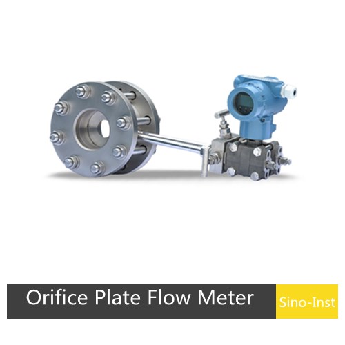
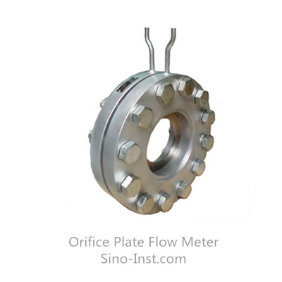
The Standard Orifice Flowmeter is a differential pressure flow measurement device with a long history of proven performance and comprehensive experimental data. It features simple construction with no moving parts, ensuring long-term stability and reliability.
Compliant with international standard ISO 5167 and Chinese national standard GB/T 2624, it can be put into use without actual flow calibration — making it unique among flow sensors.
It is widely used in industries including steam boilers, petroleum, chemicals, steel, power generation, water conservancy, papermaking, pharmaceuticals, food processing, and chemical fibers. Differential pressure flowmeters account for an estimated 75%–85% of all flow instruments in use today.
Internationally recognized standard — no real-flow calibration required before commissioning
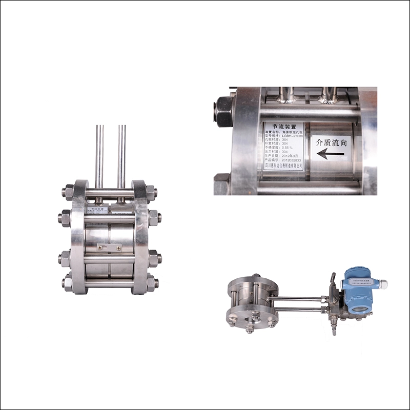
Simple, rugged structure with stable, reliable long-term performance
Wide application range covering all single-phase fluids (liquid, gas, steam) and partial mixed-phase flows
Suitable for a broad range of pipe diameters, temperatures, and pressures
Sensor and display instruments can be sourced independently, supporting modular and scalable systems
Technical Parameters
Parameter
Specification
Nominal Diameter
DN25 – DN2400 mm
Nominal Pressure
≤42 MPa
Operating Temperature
-50°C to 550°C
Aperture Ratio (β)
0.10 – 0.75
Accuracy Class
1.0 / 1.5 / 2.0
Connection
Welding, flange, threaded, or custom
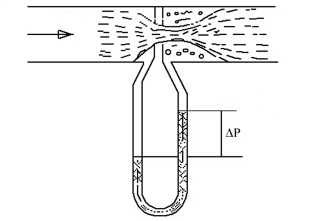
Orifice Plate Flow Meter Working Principle
When fluid passes through a throttling element (orifice plate) installed in a pipe, the flow stream contracts locally, increasing velocity at the restriction. This creates a static pressure difference (ΔP) between the upstream and downstream sides. The greater the flow rate, the larger the pressure difference. By measuring this ΔP with a differential pressure transmitter, the flow rate can be calculated based on the law of energy conservation and the continuity equation.
Order Guide
In addition to regular products, we support customization
L G B K D 50 2 (Example)
Position
Code
Meaning
1st – Product Series
L
Flow meter
2nd – Supply Form
Z
Throttling device with front and rear straight pipe sections
G
Throttling component
3rd – Throttling Type
B
Orifice plate
P
Nozzle
C
Long nozzle
W
Venturi tube
H
Quarter round hole plate
Q
Circular orifice plate
T
Lens orifice plate
S
Double orifice plate
K
Annular orifice plate
J
Wing wind measuring device
SW
Double Venturi tube
Z
Uniform velocity tube
VZ
Conical tube
X
Wedge-shaped tube
D
Porous orifice plate
4th – Pressure Tapping
K
Ring chamber pressure tapping
F
Flange pressure tapping
J
Radial distance pressure tapping
Z
Straight hole angle connection pressure tapping
B
Eight slot orifice or eight slot nozzle
H
Welded orifice/nozzle special pressure tapping
X
Current limiting orifice plate
5th – Nominal Pressure
A
0.25 MPa
B
0.6 MPa
C
1.0 MPa
D
1.6 MPa
E
2.5 MPa
F
4.0 MPa
G
6.4 MPa
H
10 MPa
T
16 MPa
6th – Nominal Diameter
—
Outer diameter × wall thickness or nominal diameter
7th – Supply Scope
—
See supply scope code table below
Supply Scope Code
Code
Scope of Supply
1
Throttling component only
2
Throttling component + clamping ring (ring chamber) pressure device + pressure short pipe
3
Throttling component + ring chamber pressure device + installation flanges + fasteners + pressure short pipes
4
Throttling component + flange pressure device or installation flanges + fasteners + pressure short pipes
Orifice plate flow meters are suitable for flow measurement of liquids, gases, and steam under single-phase conditions—including water, compressed air, natural gas, steam, oil products, and chemical process fluids.
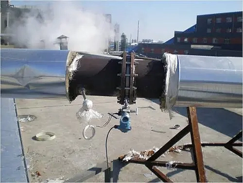
In the power industry, accurate steam flow measurement is crucial for power plant operation. A large power plant needed to measure the flow rate of high-temperature, high-pressure steam during power generation. After comparing various options, they ultimately chose Sino-Inst’s orifice plate flow meters.
Engineers at the power plant stated that the orifice plate flow meters performed exceptionally well under high-temperature, high-pressure conditions, accurately measuring steam flow. Furthermore, the orifice plate flow meters have a fast response time, enabling real-time monitoring of steam flow changes, providing vital data support for the power plant’s operation. During the power plant’s production process, the orifice plate flow meters demonstrated excellent stability, with virtually no malfunctions, significantly improving power generation efficiency and safety.
By using orifice plate flow meters, the power plant not only improved power generation efficiency but also reduced production costs. This case fully demonstrates the wide application and superior performance of orifice plate flow meters in the power industry.
Why Natural Gas Flow Measurement is Pivotal? Natural gas is a vital energy source, providing electricity to industries, homes, and businesses worldwide. High-precision natural gas flow measurement is essential for ensuring fair trade, accurate trade measurement, and safe and efficient…
In its gaseous form, Propane has numerous applications. Propane is usually used for residential heating, cooking, and powering small appliances. Industrially, propane can be separated from oilfield gas and cracking gas. It can be used as a raw material for…
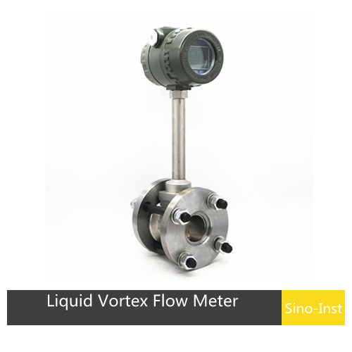
To begin with: Vortex Flow Meters for Steam Applications The requirement for high-fidelity and trustworthy flow measurement has become pivotal across various industries, especially in applications involving steam. Steam is widely used in industries such as power generation, chemical processing,…
Natural gas is a colorless and odorless hydrocarbon and an important energy source. In the production, transportation, storage, distribution, trade, and factory applications of natural gas, natural gas flow measurement is required. With many years of experience in gas flow…
The vortex flowmeter is a velocity-type flow instrument that operates based on the principle of fluid oscillation. Due to its simple structure, high accuracy, and wide range of applications, it has become popular in industrial measurement. From petrochemicals to food…
An orifice plate flow meter is a high-range differential pressure flow measurement device consisting of a standard orifice plate and a multi-parameter differential pressure transmitter. Orifice plate tapping refers to the method of extracting the differential pressure before and after…
Orifice plate flow meters perform exceptionally well in practical applications, meeting the flow measurement needs of various industries. Whether in the chemical, petroleum, power, food, or environmental protection sectors, orifice plate flow meters demonstrate advantages such as high accuracy, high reliability, and low maintenance costs. If you are looking for a reliable flow measurement device, consider an orifice plate flow meter; it may bring unexpected improvements to your production processes.
Zhang Wei, possesses 20 years of experience as an automation instrumentation engineer, specializing in the research, design, installation, commissioning, and maintenance of automation instruments.
Face to various instrument communication protocols (such as Modbus, Profibus, etc.), with solid hardware circuit design and software programming skills (proficient in C language and PLC programming). Has extensive project experience; projects he has led and participated in have all achieved outstanding results, improving product accuracy, reducing costs, and increasing production efficiency.
Possesses excellent communication and coordination skills and a strong team spirit, enabling him to quickly respond to customer needs and provide high-quality automation instrumentation solutions.