-1.jpg)
Correct installation of Magnetic flowmeter can ensure accurate flow rate measurement.
Are you ready to install an electromagnetic flowmeter? Then this electromagnetic flowmeter installation instructions are exactly what you need. The magnetic flowmeter installation instructions here apply to magnetic flowmeters supplied by Sino-Inst. Made in China. If you have any questions about the measurement and installation of electromagnetic flow meters, please feel free to contact us.
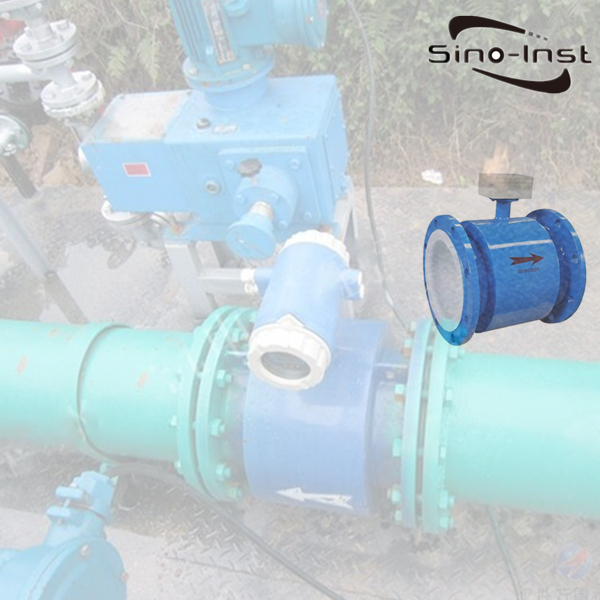
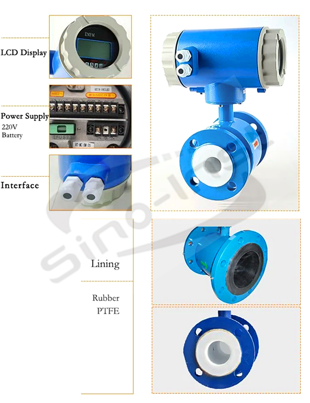
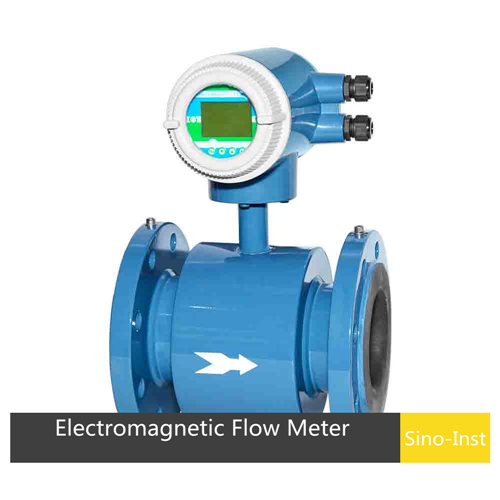
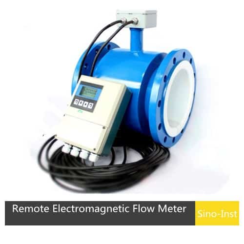
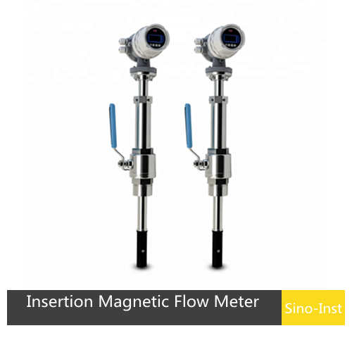
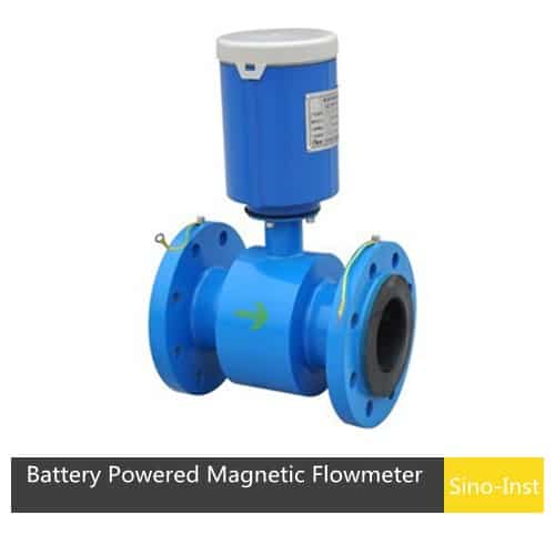
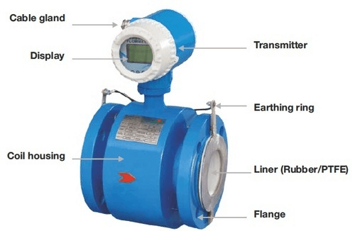
A Magnetic flow meter, also called electromagnetic flow meter, mag flow meter, or magmeters. A magnetic flow meter is a volumetric flow meter that works with principle of magnetic technology. Magnetic flow meters do not have any moving parts. An electromagnetic flowmeter consists of two parts: Electrode (sensor) and Transmitter. Installation types of magmeters could be: Compact, remote, insertion.
The electromagnetic flowmeter is mainly used to measure the flow of conductive media with good fluidity. The electromagnetic flowmeter is divided into a insert type and a pipeline type. Pipeline and insert electromagnetic flowmeters have the same amount of installation requirements.
Installation steps of electromagnetic flowmeter
- Select the correct installation location.
- Installation inspection. After installation, check whether the pipeline is installed correctly and whether the connections are reliable, especially the inspection of the ground wire.
- Power on to warm up. After the electromagnetic flowmeter is powered on and warmed up for 20 minutes, the electromagnetic flowmeter can normally measure normally.
- Zero tracking. In order to maintain the accuracy of the electromagnetic flowmeter, zero tracking is required. If the measuring tube of the electromagnetic flowmeter is filled with a medium, zero point calibration can be performed and then saved (confirmed).
However, you need to know more if you want to install the electromagnetic flowmeter correctly.
Basic knowledge of electromagnetic flowmeter installation

Requirements for the installation environment
- The electromagnetic flowmeter should be installed in a place where the temperature changes greatly or the device is exposed to high temperature radiation. If installation is necessary, measures must be taken for heat insulation and ventilation;
- The electromagnetic flowmeter is best installed indoors. If it must be installed outdoors. Avoid rainwater pouring, flooding and sun exposure. Must have moisture and sun protection measures;
- The flowmeter, especially the flowmeter with intelligent liquid crystal display screen, should be installed in a location that avoids direct sunlight. The ambient temperature should be between 5C and 55C.
- The electromagnetic flowmeter should be avoided in the environment containing corrosive gas. When installation is necessary, ventilation measures must be taken.
- In order to facilitate the installation, maintenance and maintenance, ample installation space is required around the flowmeter;
- The installation place of the electromagnetic flowmeter should avoid magnetic fields and strong vibration sources. If the pipeline has a large vibration, there should be fixed pipeline supports on both sides of the flowmeter. Install the flowmeter in a place without strong electromagnetic field radiation. Avoid devices such as electric motors, transformers, frequency converters, etc. that are likely to cause electromagnetic interference. The measuring principle of the flow meter is based on Faraday’s law of electromagnetic induction. The original signal it generates is very weak, less than millivolts. If there is strong electromagnetic field radiation near the flowmeter, it will affect the accuracy of the measurement and may not even work properly.
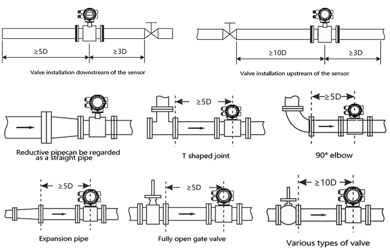
- Length of straight pipe. Be careful to avoid eddy current generating components, such as various valves, elbows, bypasses, etc. Try to extend the straight pipe section upstream and downstream of the flow meter. Install rectifiers if necessary. Make sure that the upstream straight pipe section of the flowmeter is more than 5 DN (measurement pipe diameter), and the downstream is more than 2 DN.
- The conductivity of the liquid must be uniform and stable. Do not install the flow meter in a place where the conductivity of the measured fluid is extremely uneven. If a different medium is injected upstream, it will lead to uneven conductivity and affect the measurement. In this case, it is recommended to move the injection port downstream. If it must be injected upstream, it should be kept as far away from the flow meter as possible. Generally, it is better to keep a distance of more than 20 DN to ensure that the liquid is fully mixed uniformly.
- Keep the electrode axis level. The measuring electrode plane must be level. This prevents short-time insulation between the two electrodes due to air bubbles.
- No air bubbles. Ensure that no air bubbles are generated when the flowmeter is installed in the pipeline design.
- The pipeline of the flowmeter is full. The flowmeter can be installed horizontally, vertically and obliquely. However, the pipeline structure should ensure that the measuring tube is always filled with liquid (full tube). When designing the pipeline, pay attention to ensure that there are no air bubbles in the measuring pipe section, otherwise it will cause unstable measurement and excessive deviation.
Installation pipe section of electromagnetic flowmeter
Requirements for straight pipe sections of electromagnetic flowmeters:
Requirements for piping of electromagnetic flowmeter:
Requirements for the bypass pipe of the electromagnetic flowmeter:
Installation Method
- It should be installed at the lower part of the horizontal pipeline and vertically upwards, avoiding the installation at the highest point of the pipeline and vertically downwards;
- It should be installed on the rise of the pipeline;
- Install in the open discharge pipeline, it should be installed in the lower part of the pipeline;
- If the pipe drop exceeds 5m, install an exhaust valve downstream of the sensor;
- Control and shut-off valves should be installed downstream of the sensor. It should not be installed upstream of the sensor;
- The sensor must not be installed at the inlet and outlet of the pump, it should be installed at the outlet of the pump.
- The installation position of the electromagnetic flowmeter should be installed according to the actual needs of the site, but the electrode axis must be installed horizontally.
- The electromagnetic measuring tube must be completely filled with the pipe section during the working time on site.
- The flow direction of the measured medium should be consistent with the direction of the arrow on the electromagnetic flowmeter.
- If the measured medium contains solid particles or slurry, it is recommended to install it vertically (flowing from bottom to top). Avoid depositing solid particles in the measuring tube of the flow meter.
Installation requirements for insert electromagnetic flowmeters
- Requirements for straight pipe sections. Inlet / exit straight pipe section: the inlet should be ≥10 × DN; the outlet should be ≥5 × DN
- Requirements for grounding points. In order to make the meter work reliably and improve the measurement accuracy, it should not be disturbed by external parasitic potentials / the sensor should be well grounded. Grounding resistance is less than 10. (If the metal pipeline is well grounded, no special grounding device is required)
- Insert the electromagnetic flowmeter according to the situation of the pipeline. Where continuous flow loading or unloading is required or medium is not allowed to overflow, a ball valve must be installed. That is, a insert electromagnetic flowmeter with a ball valve structure is selected.
- Make a hole diameter of 50 in the pipe and prepare to weld the welded pipe to the hole in the pipe. Simple installation of insert electromagnetic flowmeter. Can flow continuously. With pressure openings on site. With absolute installation advantages and price advantages.
- Flow detection is only related to the insertion depth. Therefore, the flowmeter has wide versatility and strong interchangeability. One model is suitable for fluid measurement requirements of various specifications of pipelines.
Precautions
Featured Magnetic flow meters
Technical Support
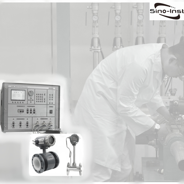
Flowmeter Calibration & Recalibration
Flowmeter Calibration & Recalibration are performed in accordance with various flowmeter verification procedures. For current flowmeters, the standard throttling device does not need to be tested. The remaining flowmeters are almost always tested when they leave the factory. The flowmeter has been verified according to the Calibration procedures before leaving the factory.
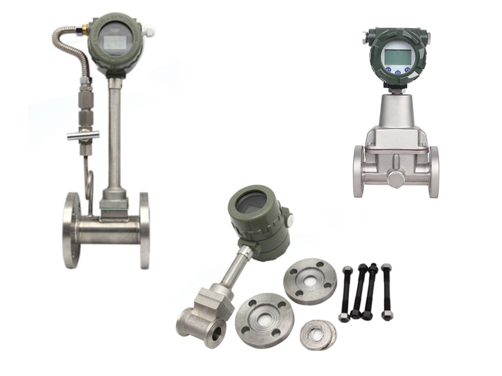
Vortex Flowmeter Technology
Best Technology Guide to Vortex Flow Meters. Vortex flow meters are suitable for measuring steam as well as a variety of liquids and gases. As fluid moves across a vortex meter shedder bar, vortices form. The frequency of the vortices shedding is proportional to the fluid velocity.Even for the steam flow rate, Vortex flow meters are the perfect choice. Pressure and Temperature compensation ensure measurement accuracy. When measure steam or gas flow in pipes with variable operating pressure and temperature.
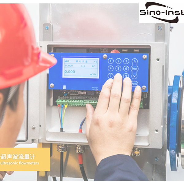
Water Flow Measurement Solution-Ultrasonic Flowmeter
Ultrasonic flow meters are based on the speed at which ultrasonic waves are transmitted by a flowing medium. A flowmeter developed by the sum of the average velocity of the measured medium. And the vector of sound waves moving in a stationary medium. Ultrasonic flow meters are non-intrusive flow meters. .
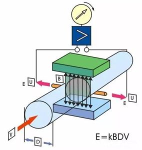
How does a magnetic flowmeter work?
Magnetic flow meters use the principle of Faraday’s Law of Electromagnetic Induction to measure the flow rate of liquid in a pipe. In the magnetic flowmeter pipe parts, a magnetic field is generated, and channeled into the liquid flowing through the pipe. Faraday’s Law states that the voltage generated is proportional to the movement of the flowing liquid. A conductor moving through a magnetic field produces an electric signal within the conductor. And the singal is proportional to the velocity of the water moving through the field. As fluid flows through the magnetic field, conductive particles in the fluid create changes. This variation is used to measure and calculate the velocity of water flow through the pipe. When the fluid moves faster, more voltage is generated. The electronic transmitter processes the voltage signal to determine liquid flow.
Magnetic Flow Meter Construction
Q&A
- The installation location should be selected to avoid electromagnetic interference. The installation location of the sensor and transmitter and the cable laying should be as far away as possible from equipment that is likely to generate strong electromagnetic fields. Such as high-power motors, transformer facilities, frequency conversion equipment, etc.
- The mass flow sensor should be installed in such a way that the flow direction identification of the sensor is consistent with the flow direction. Make the arrows point in the same direction as the flow configured inside the transmitter. Note: The mass flow meter can be used in both directions. If the installation direction is opposite to the actual flow direction, modify the flow direction configuration in the transmitter.
- Coriolis mass flowmeter is a flow meter which is measured according to the vibration principle of the measuring tube. Therefore, when installing the sensor, you should consider making strong support on the two sides of the process pipeline near the flange (about 2 to 10 times the pipe diameter). Avoid vibration of the meter and related pipelines. If strong pipeline vibration is unavoidable, it is recommended to isolate the pipeline system from the instrument sensor with a flexible pipe.
- Since the mass flow meter works according to the Coriolis force principle, in order to avoid the influence of gravity on the measurement accuracy. Whether the measuring tube of the mass flow meter is installed upwards or downwards, the measuring tube must be kept vertical or horizontal to the ground plane as much as possible.
- The flange surfaces of the connection should be parallel to each other during installation. The two flanges should be centered on the same axis to avoid additional stress. It is strictly forbidden to straighten the upstream and downstream process pipes with sensors. Otherwise it will affect the measurement and even damage the sensor.
- It is recommended to install shut-off valves and bypasses on the upstream and downstream pipelines of the sensor to facilitate zero adjustment, routine maintenance, and to ensure that the sensor can also be fully piped when it is not working. Use a regulating valve downstream of the flow meter for flow control.
- The installation direction of the sensor. Make sure that the measured medium can completely fill the sensor. Don’t collect gas for liquid. It is not necessary to accumulate liquid for gas, and it is easy to evacuate thick, dirty, high freezing point media. Low point valves can also be installed on both sides as required.
- Newly installed pipes or pipes that have not been used for a long time and have just been activated. The entire pipeline must be purged (especially upstream) before the mass flow meter is installed. Ensure that no welding slag or debris remains in the pipeline.